Flex setup instructions
Matthew Oppenheim - matt@mattoppenheim.com
github https://github.com/hardwaremonkey/microbit_flex
Safety
Normal safety practice should be followed with the AAA batteries if they are used – keep them dry.
System overview
The flex system consists of two modules - the sensor module and the switch module. The participant uses the flex sensor which is attached to the sensor module. When the flex sensor is flexed beyond an adjustable threshold, a radio signal is sent from the sensor module to the switch module. The switch module connects to a switch adapter cable e.g. a JoyAdapter cable. The switch adapter cable is plugged into the laptop or tablet running the software that we want to control e.g. Grid 3. The switch module receives the radio signal from the sensor board and triggers the switch adapter cable. The switch adapter cable sends a switch signal to the attached communication device.
Both of the modules are made using a BBC micro:bit board slotted into an expansion board. This board is given to 11-12 year olds to learn programming at school.
The micro:bit optionally has a yellow 'kittenbot' cover. The expansion boards are housed in a 3d printed case.
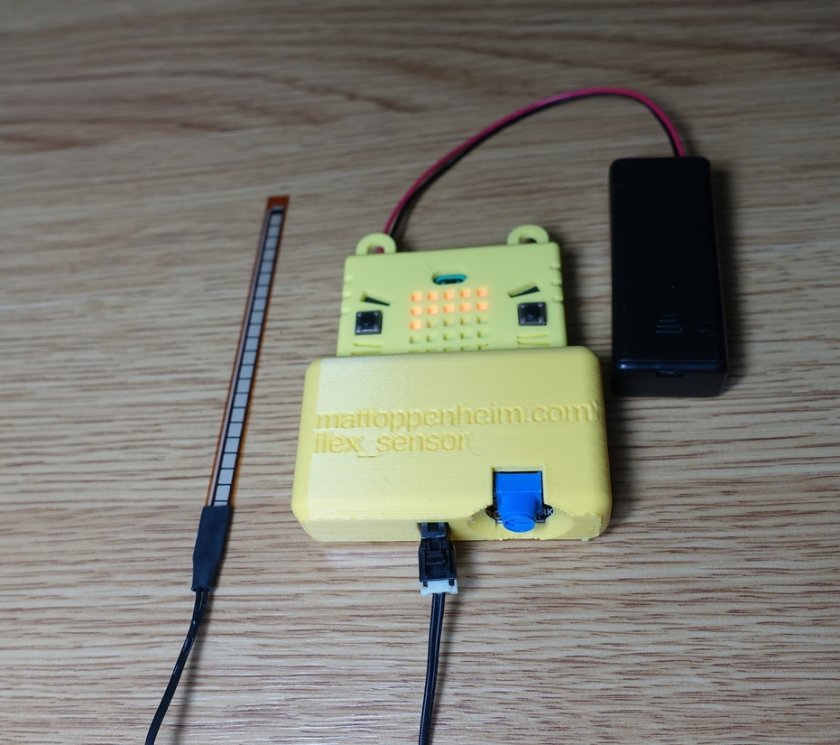
The flex sensor module is shown in the picture below.
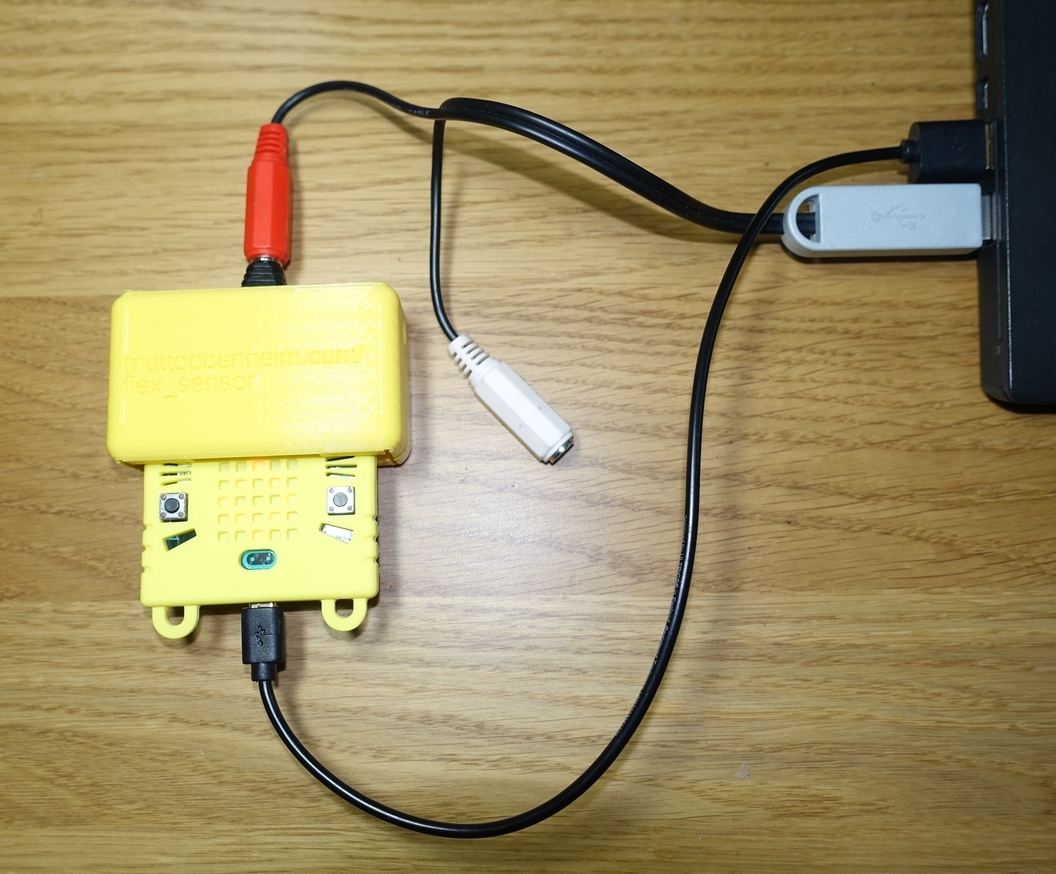
The switch module is shown in the picture below, attached to a JoyAdapter cable.
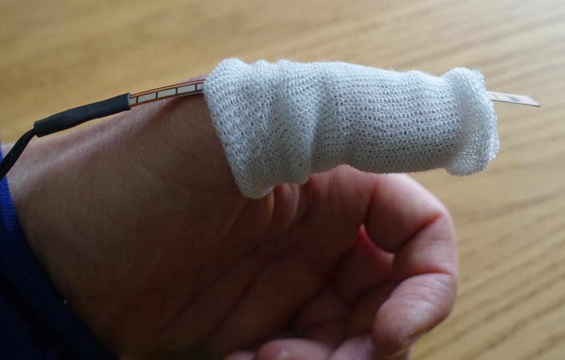
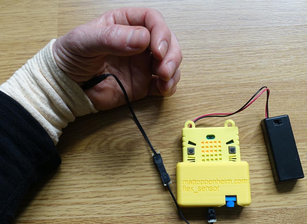
Two possible ways to use the flex sensor are shown below.
Operating instructions summary
-
Place the flex sensor on the participant.
-
Set the amount of bend needed to create a trigger signal using the blue knob on the flex module and the buttons on the micro:bit.
-
Connect the switch board to a switch adapter cable connected to the communication device.
How the flex sensor works
The resistance of the flex sensor changes as it is bent. This change in resistance is measured using the micro:bit. When the change in resistance passes a setpoint, a trigger is sent to the switch module.
The setpoint which causes the trigger is adjustable.
Flex sensor module components
micro:bit plugged into an expansion board
case
battery pack for 2xAAA connectors
flex sensor
cable to connect the flex sensor to the expansion board
Switch module components
micro:bit plugged into an expansion board
case
battery pack for 3xAAA connectors (optional)
USB cable (optional - either the battery pack or the USB cable should be used to power the module)
System summary
The switch module connects with the switch adapter cable using the audio plug. When a trigger signal is received from the sensor module, the switch module acts to send a switch signal through the switch adapter cable to the attached communication device. A JoyAdapter cable was used for testing.
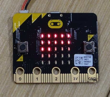
When a flex is detected, a checkerboard pattern is shown on the LEDs on the micro:bits on both the sensor board and the switch board, as shown in the figure below. A switch signal is sent to the adapter cable at the same time.
Switch module
This module is powered using either a 3xAAA battery pack or from the USB socket.
Setup
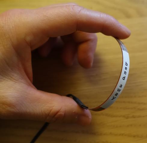
The flex sensor only measures bend when bent in one direction. There is a sticker on the flex sensor saying 'bend away'. The sticker should be on the top of the bridge shape formed when the sensor is bent. Please see the photo below. Bending the sensor in the opposite direction does not cause any damage, it is just that the flex sensor does not respond in this direction.
The flex sensor plugs into the flex sensor module board using a keyed connector.
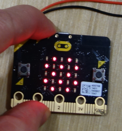
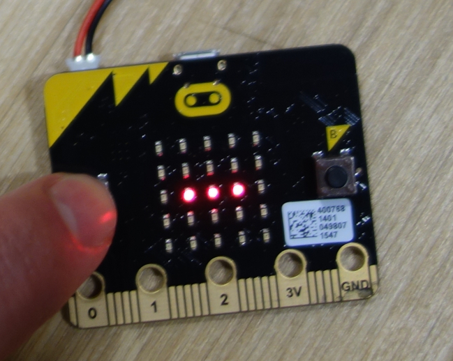
There are bright LEDs and faint LEDs on the micro:bit display at power-up. As the flex increases, the faint LEDs will sequentially become bright. The flex sensor will send a trigger when there are only bright LEDs on the display. The more faint LEDs that are on before bending the flex sensor, the more that the flex sensor needs to be bent to send a trigger.
A photo showing the bright and faint LEDs on the micro:bit is shown below.
The setpoint which causes a trigger to be sent is adjusted using the blue knob on the flex sensor board. This controls how many bright LEDs are on the display without the sensor being flexed.
The number of faint LEDs on the display is set using the A and B buttons on the micro:bit.
Increasing how much bend is needed to create a trigger
Pressing the B button causes a single extra faint LED to be added to the display. A '+' symbol is displayed each time the button is pressed. Please see the picture below.
This acts to increase the amount of flex needed to cause a trigger.
Decreasing how much bend is needed to create a trigger
Pressing the A button causes a single faint LED to be removed from the display. A '-' symbol is displayed each time the button is pressed. Please see the picture below.
This acts to decrease the amount of flex needed to cause a trigger.
Use
Before use, ensure that there are more faint LEDs showing than bright LEDs.
One possible application is to have the flex sensor pre-bent at the 'rest' position and during use the sensor is further flexed. The current system allows this to be setup.
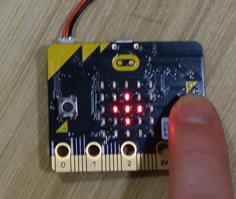
During use, the switch module shows a diamond pattern, as shown in the photo below.
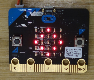
When a flex is detected, a checkerboard pattern is shown on both the flex and the switch module displays. This is shown in the photo below.
Self-test
Pressing both the A and B buttons at the same time simulates a flex being detected. Use this to test the operation of the adapter cable.
Troubleshooting
If the micro:bit pulls out of the expansion board, just plug it back in. There is a 3D printed clip to prevent the board from easily coming out of the expansion board.
Check that the micro:bit is plugged in to the expansion board the correct way up. The battery packs sit on the top of the expansion board case. The LEDs and buttons on the micro:bit should point up.
If you are using an untested triple AAA battery pack with the switch board, check that the polarity of the batery pack connector is correct. Some off the shelf battery packs have the polarity the wrong way around for the board. Take off the kittenbot cover from the micro:bit and look at the battery pack connector socket on the micro:bit. The polarity signs are printed on the circuit board. This will not damage the board - it will not work though! I use a small screwdriver blade to pull up the plastic latch on the back of the connector above each crimped pin, pull out each crimped pin, then swap over which hole each one goes to in the connector.